Free Project services
ACO has an established Technical Services Department with many years experience advising on access covers. This free service is offered with no obligation and is supported with extensive, high quality information, brochures and technical documentation.
Services offered include:
- Multipart Design Request (see below)

Multipart Scheduling & Rebate Drawings
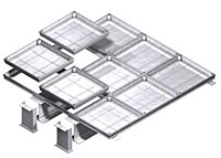
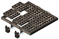 ACO can issue customers with a CAD technical drawing showing the necessary requirements for the construction of the rebate prior to the installation of the multipart. Allowances are made for the placement of both the side and end frames; and the structural beams underlying the joists.
On the drawing, all covers are numbered so that the installer may position and remove them in the correct sequence before pouring and formwork stripping operations.
In order to produce a drawing , the following information is required:
- Pit clear opening
- Load class
- Position of obstacles (that will restrict cover removal) and depth/width restrictions (in the slab)
 CAD drawings provided show the:
- Multipart cover plan
- Slab cross section along the width and length of the multipart
CAD printout provides:
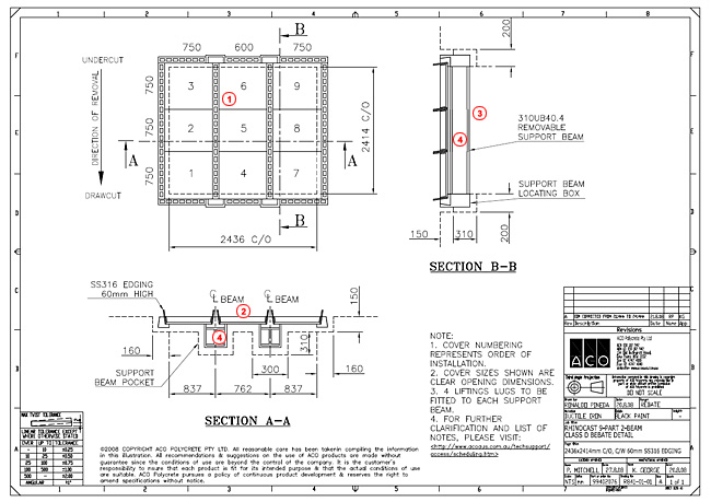
- Multipart cover plan showing cover placement / removal sequence
- Slab cross section along width of multipart
- Slab cross section along length of multipart
- Removable structural beam